

Gleason Spiral Bevel Gears Calculation
 May 03, 2017|
 View:15564
Changzhou Baoxin Gleason Spiral Bevel Gears Calculation
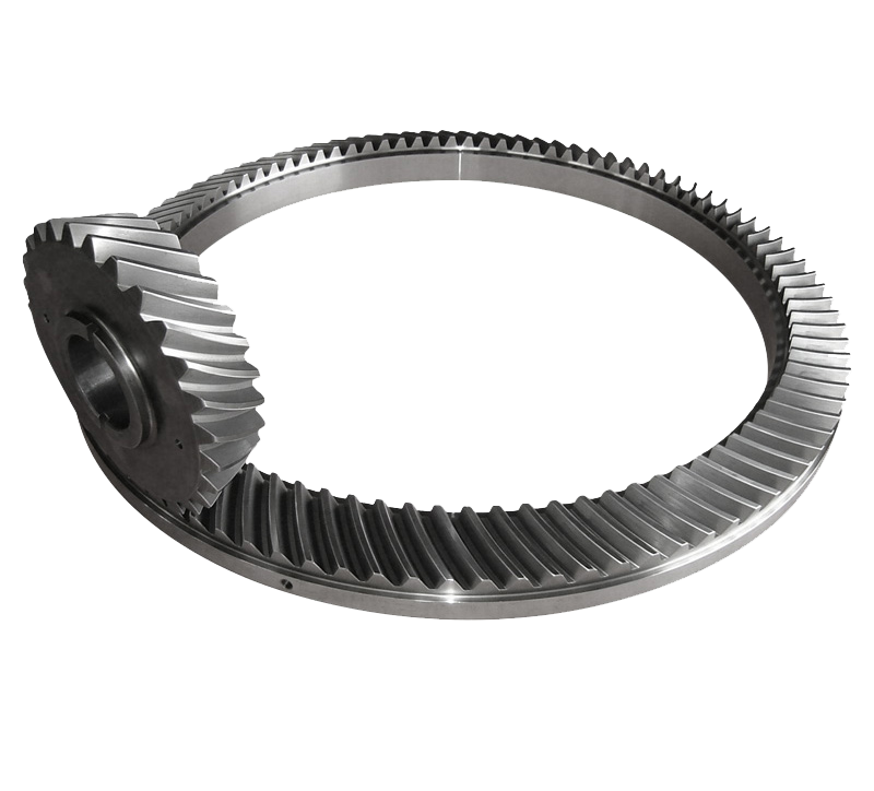
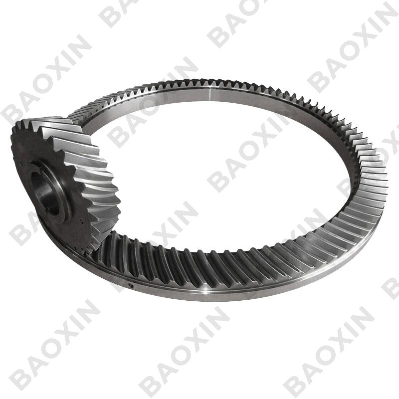
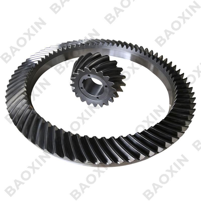
A spiral bevel gear is one with a spiral tooth flank as in Figure 1. The spiral is generally consistent with the curve of a cutter with the diameter dc. The spiral angle β is the angle between a generatrix element of the pitch cone and the tooth flank. The spiral angle just at the tooth flank center is called the mean spiral angle βm. In practice, the term spiral angle refers to the mean spiral angle.
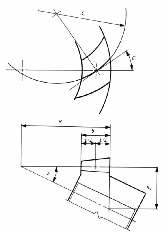
Fig.1 Spiral Bevel Gear (Left-hand)
All equations in Table 2 are specific to the manufacturing method of Spread Blade or of Single Side from Gleason. If a gear is not cut per the Gleason system, the equations will be different from these.
The tooth profile of a Gleason spiral bevel gear shown here has the tooth depth h = 1.888m; tip and root clearance c = 0.188m; and working depth hw = 1.700m. These Gleason spiral bevel gears belong to a stub gear system. This is applicable to gears with modules m > 2.1.
Table 1.8 shows the minimum number of teeth to avoid undercut in the Gleason system with shaft angle Σ = 90° and pressure angle αn = 20°.
Table 1.8 The minimum numbers of teeth to prevent undercut β=35°
If the number of teeth is less than 12, Table 1.9 is used to determine the gear sizes.
Table 1.9 Dimentions for pinions with number of teeth less than 12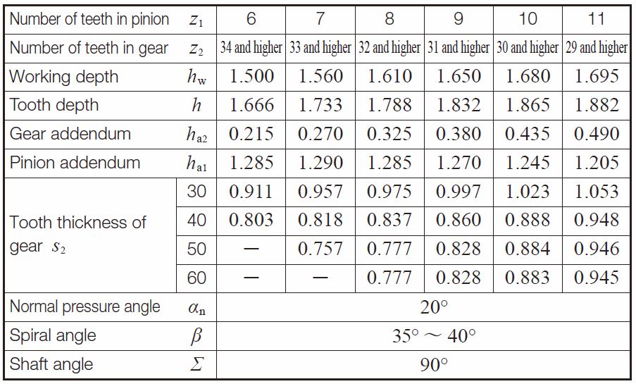
Table 2 shows the calculations for spiral bevel gears in the Gleason system
Table 2 The calculations for spiral bevel gears in the Gleason system
| No. | Item | Symbol | Formula | Example | |
| Pinion (1) | Gesr (2) | ||||
| 1 | Shaft angle | ∑ | Set Value | 90 deg | |
| 2 | Module | m | 3 | ||
| 3 | Normal pressure angle | αn | 20 deg | ||
| 4 | Mean spiral angle | βm | 35 deg | ||
| 5 | Number of teeth and spiral hand | z | 20 (L) | 40 (R) | |
| 6 | Transverse pressure angle | αt | 23.95680 | ||
| 7 | Reference diameter | d | zm | 60 | 120 |
| 8 | Reference cone angle | σ1 σ2 | 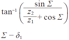 | 26.56505 deg | 63.43495 deg |
| 9 | Cone distance | R | 67.08204 | ||
| 10 | Facewidth | b | It should be less than 0.3R or 10m | 20 | |
| 11 | Addendum | ha1 ha2 | 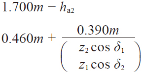 | 3.4275 | 1.6725 |
| 12 | Dedendum | hf | 1.888m – ha | 2.2365 | 3.9915 |
| 13 | Dedendum angle | θf | tan^-1( hf / R ) | 1.90952 deg | 3.40519 deg |
| 14 | Addendum angle | θa1 θa2 | θf2 θf1 | 29.97024 deg | 1.90952 deg |
| 15 | Tip angle | σa | σ + θa | 29.97024 deg | 65.34447 deg |
| 16 | Root angle | σf | σ – θf | 24.65553 deg | 60.02976 deg |
| 17 | Tip diameter | da | d + 2ha cos σ | 66.1313 | 121.4959 |
| 18 | Pitch apex to crown | X | R cos σ – ha sin σ | 58.4672 | 28.5041 |
| 19 | Axial facewidth | Xb | 17.3565 | 8.3479 | |
| 20 | Inner tip diameter | di | 46.1140 | 85.1224 | |
All equations in Table 2 are also applicable to Gleason bevel gears with any shaft angle. A spiral bevel gear set requires matching of hands; left-hand and right-hand as a pair.
(4) Gleason Zerol Bevel Gears
When the spiral angle bm = 0, the bevel gear is called a Zerol bevel gear. The calculation equations of Table 4.16 for Gleason straight bevel gears are applicable. They also should take care again of the rule of hands; left and right of a pair must be matched. Figure 4.13 is a left-hand Zerol bevel gear.
Fig. 1.3 Left-hand zerol bevel gear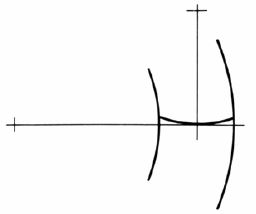
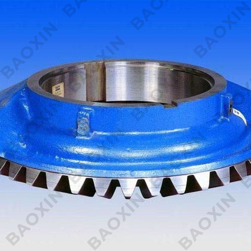
Baoxin's Manufacturing Capabilities
Leveraging German Gleason CNC gear milling machines to achieve high-precision physical realization of theoretical parameters:
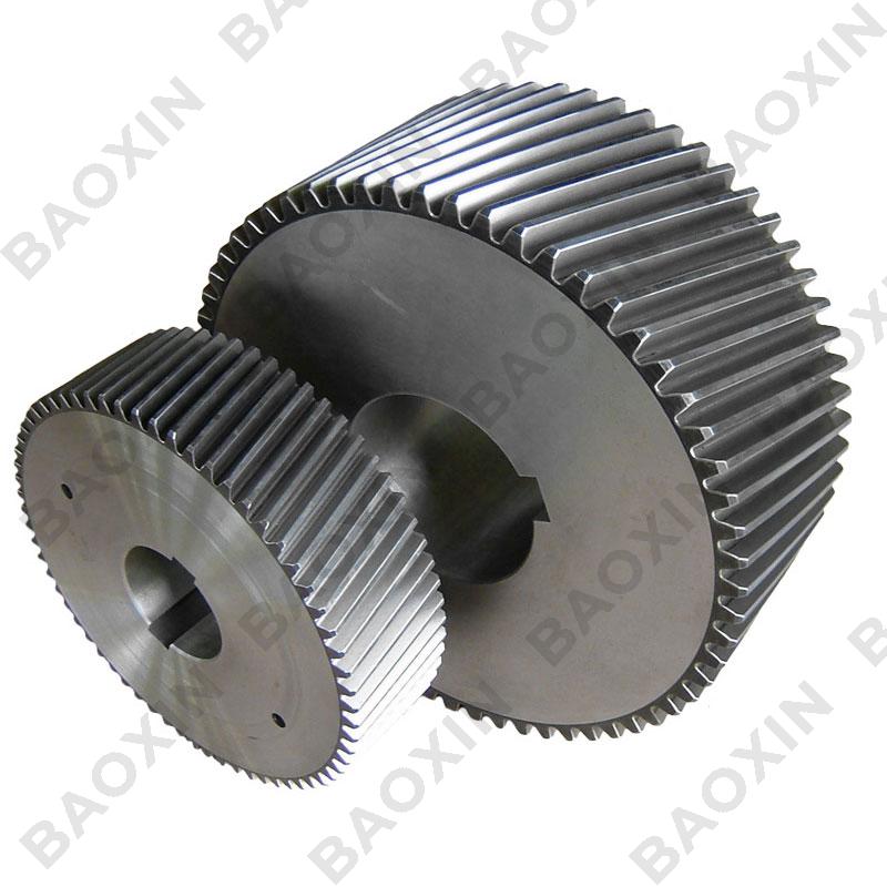
Tooth Surface Processing
Helical tooth flank profile tolerance ≤0.015mm (exceeds DIN 3965 Class AA)
Crowning modification along tooth direction to compensate for elastic deformation (specialized for rolling mill gears)
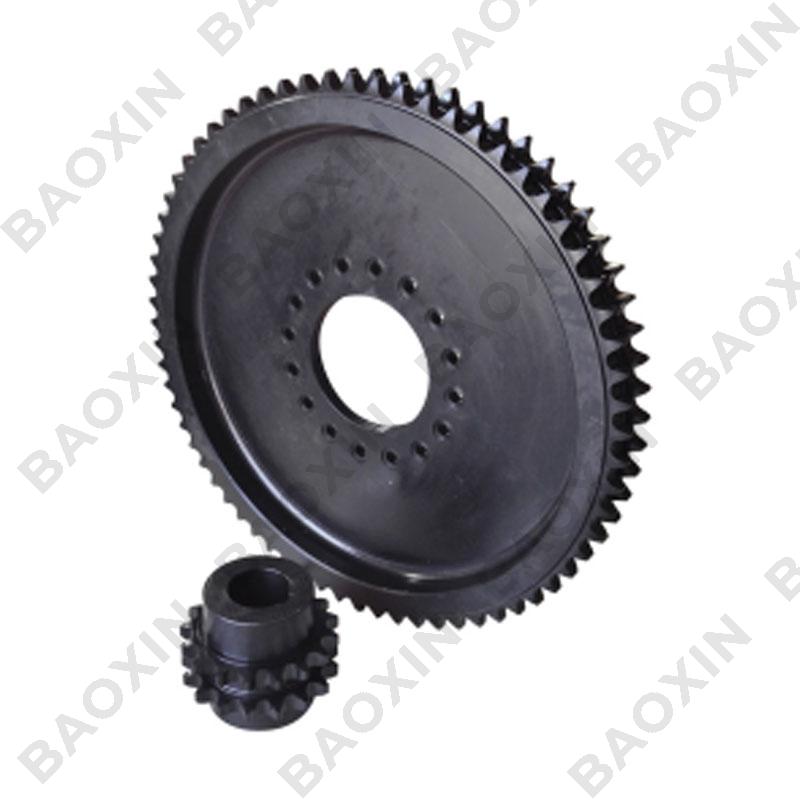
Material and Heat Treatment
Base material: 18CrNiMo7-6 carburizing steel (surface hardness HRC 60-62)
Process: Controlled atmosphere nitriding with tooth root residual compressive stress ≥800MPa
Inspection System
Full-parameter scanning via gear measuring center (Klingelnberg P65)
Fatigue bench testing: 10^7 cycle loads (equivalent to 20 years of operational conditions)
I want to comment
Recent News
1.Helical Gear PT
2017-04-262.Reducer gears
2017-04-273.The essential knowledge needed for Baoxin gear design
2017-05-034.Gleason Spiral Bevel Gears Calculation
2017-05-035.Optimizing Efficiency: How Spiral Bevel Gears Improve Power Transmission
2023-07-206.What is a spiral bevel gear used for?
2025-01-22


View More(Total0)Comment lists